
A comprehensive tutorial for installing a TK102 GPS tracker inside a Phantom 2.
Disclaimer: This is a tricky mod and most definitely NOT a walk in the park. It requires lots of time and patience and making modifications to your Phantom’s shell. If you are not comfortable with things like this, don’t do it and leave the tracker fitted externally. There is always going to be some risk doing things like this, so please be sure you understand this if you want to proceed. If you mess up, take your time and think things through. If you want to stop and ask a question I’m happy to try and help you out, so stop where you are and drop me a comment below if you need to. Lastly, I take no responsibility for anyone’s actions / consequences. I am simply detailing the processes I went through. If you want to use this to help you do a similar mod, go ahead but it’s obviously at your own risk : )
Tool list
- Large flat head screwdriver
- Small flat head screwdriver
- Hex screwdriver (2.0 size)
- Crosshead screwdriver (000 size)
- Multitool such as a Dremel with a circular cutting blade and small drill bit
- Sharp craft knife
- Masking tape
- 2x small elastic bands
- Vacuum cleaner (optional)
- Patience (not optional)
- Time (not optional)
Disassemble the TK102
- Remove the cover to reveal the battery compartment.
- Remove the battery and sim card.
- Locate the screw and remove it (this is usually hidden underneath a little circular sticker with Chinese text on it next to the sim holder).
- With a small flat headed screwdriver gently lift up and remove the inner plastic housing to reveal the circuit board.
- Prise off the curved plastic part from the top of the unit. You’ll probably be best off using a flathead screwdriver and will have to apply some force here. Mine snapped in half and fell off cleanly. Generally be very careful with this as the curved plastic covers the GSM antenna which you will need to keep intact.
- Gently create a hole large enough to be allow you to slide the antenna strip free (fig.1). You could use some snips here, I chose to slowly pick away a hole with a sharp blade, then gently folded the antenna strip lengthways so it could slide through without dislodging the attached thin red wire. Take your time and watch your fingers — you will need those ; )
-
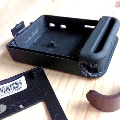
fig.1 -
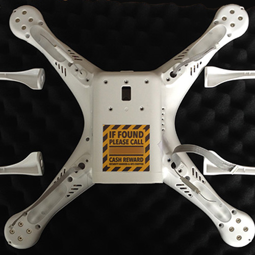
fig.2 -

fig.3
Disassemble the Phantom
- This is the easy part. First flip your Phantom over and rest it on a soft surface.
- Next, remove the landing skids (fig.2). There are two crosshead screws for each. Probably a good idea to snap a quick photo here in case you need to remember the exact location of all the cables etc. for later.
- Gently slide all the cables through the holes to free the skids. Put them to one side out of the way.
- You now need to remove the top half of the Phantom. With it still upside down, remove the three hex nuts from each arm (these surround the LED windows) but make sure you leave the four nuts which hold the motors in place for now. Finally unscrew the tiny crosshead screws which are at the top of the arms, just in front of the motors.
- Flip the Phantom over and gently lift the top half, just a little, then unplug the GPS plug from the main board to free the lid completely. Put this to one side out of the way.
Remove the Phantom’s guts
I won’t go into to much detail here as this is a lengthy procedure. The best thing to do is watch a few videos. Here is a good one: http://youtu.be/A0QQctngzSg
The guy is doing a P1 to P2 shell conversion but the majority of what he is showing will apply for this mod. The key differences are a P2 / Vision will have a fixed power plug assembly and a different USB socket to disassemble. The guy in the linked video had replaced his stock RX with an aftermarket system, if you have too, you will already know how to remove it. If not, just remove the stock RX board prior to the last step, the power plug assembly.
For reference, the image above (fig.3) above shows the locations of the screws you’ll need to remove.
The power plug thing is a little tricky, here’s what I did:
Once you have removed all the screws + nuts (and motor nuts) which hold all the guts in place, you will not be able to remove everything fully until you release the power plug assembly by removing it’s two screws. Essentially the red/black power leads are a tight fit and therefor will not be allowing much movement here, so you’ll need to gently move the main board into a position which allows you to access the two screws which hold the power plug assembly in place. Take your time and don’t force anything, there will be a way with a long screwdriver but just be mindful to try and keep the motors and boards from falling around. Also be aware that you can only do this when everything, including the motors, are loose/free. This will make more sense when you are actually doing the procedure.
Once the two power plug assembly screws are out, carefully thread all the wires (compass, gimbal etc.) up through the lower shell. Then you can gingerly remove all the guts as best you can, and put them somewhere safe well out of the way. Do not let the motors get twisted.
Modify the inside of the shell
Nb. This procedure is very tricky and needs much care as you can seriously injure your self.
Please be careful!
- You need to remove enough of the plastic ribs on the left hand side (with the battery opening facing towards you) to create a good space to house the tracker. I used a Dremel style multitool. It’s not easy to fully access these plastic ribs with a device like this so don’t be tempted to go mad with the cutter — try to work out a way to do what you can. I opted to first slice inwards with the lower shell positioned with the battery access hole to the right and USB hole on the left.
- I carefully sliced into the ribs a few times to remove as much plastic as I could without doing any damage to the inside if the shell. Seriously, if you are using a multi tool please be extremely careful and don’t put your hands at risk either. Just take baby steps.
- Once I was satisfied I couldn’t use the cutter any more, I then switched out to a small drill bit. Nb. before changing bits remember to fully unplug your multitool from the mains / remove the battery if cordless. Standard practice for things that can damage your maulers!
- I then slowly used the drill bit to carve away more of the plastic (fig.4). You can get it all out, again just take your time and be very careful not to hack away at anything important like the battery wall, and the poles for holding in the main board. Take a look at the before and after images to get a good idea how much plastic you will need to get rid of to create sufficient space.
* A useful tip; have a vacuum cleaner on standby to get rid of the shrapnel as you go, it keeps your workspace nice and tidy.
If you do not have a multitool, or do not want to use one — you will have to somehow remove this plastic with a knife. Once again exercise extreme caution as you can easily injure yourself. Please be careful either way. I told you this was a tricky step!
Once you’re done, get all the bits of plastic out (fig.5). A vacuum cleaner is the best bet here. Failing that, just blow and brush it all out.
-
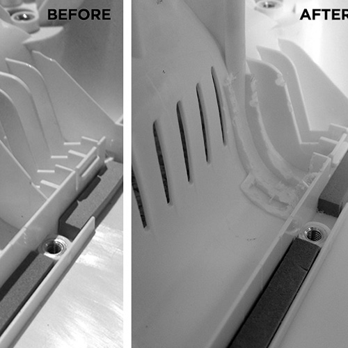
fig.4 -
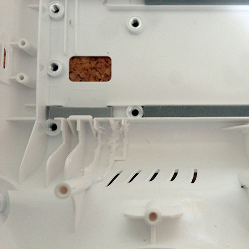
fig.5 -
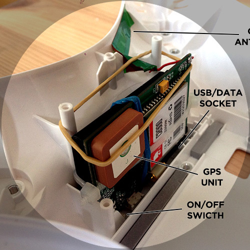
fig.6
Preparing the tracker and shell for access
Option 1: The guy who inspired my mod (info here) soldered a lead / plug to his TK board to allow battery charging with an external charger.
Option 2: I decided to utilise the USB / data socket which is already on the TK’s board to allow me to charge the battery when needed. The USB lead you get with the device will charge the battery fine, Just to be certain I’ve tested the battery with a multimeter before / after plugging-in, so you’re good.
Either way you need to cable tie the battery onto the TK’s board. I did this laterally to firmly keep the battery in place, with it’s contacts firmly pressed onto the board’s connection point. In case of any vertical movement I added a small elastic band vertically to ensure everything stays in place. In order to provide access to the USB / data socket, and the on/off switch, I positioned the unit as pictured. A slight concern was the GPS component was facing inwards, but it seems to be working fine so far, GPS signals work fine through plastic.
- If you choose to use my method, you will need to drill a small hole on the underside of the phantom which lines up with the on/off switch so you can power up/down the tracker with a paper clip. Take your time to get the positioning right. Drill from the inside of the shell (from the top) using the lowest speed setting on your multi tool. Add some masking tape to the plastic to prevent drill bit slippage. Be careful not to; a) drill into your hand, b) drill into the battery wall / poles etc. If you’re not using a multitool, you’ll need to work out a way to punch a small hole through. I would definitely not recommend using a power drill.
- You will also need to make a slot to enable plugging in the USB lead to charge the TK. Now this is where I had to make a compromise. Essentially the positioning of the unit meant the slot I created was just underneath where the H3-2D bracket is bolted on, as you can see above. Ultimately this means I will have to remove three of the bracket’s screws and twist it out of the way (or remove it completely) when I need to charge the TK. It’s not ideal but I’m okay with this as the battery lasts for quite a while especially as the unit is off most of the time. I tried to change the orientation of the TK to avoid this issue, but found it just didn’t fit snugly. There may be a way for you to try and get this to work, up to you if you want to play around but I ran into issues. You could always go for this method and make a custom plug, fitting it somewhere easier to access.
-
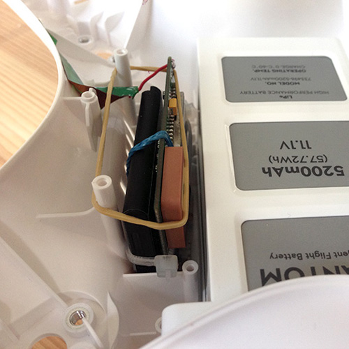
fig.7 -
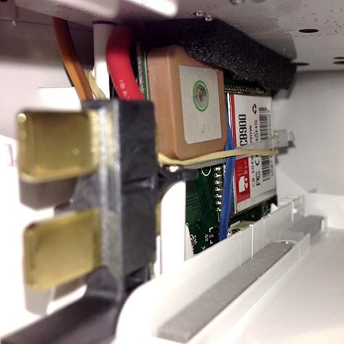
fig.8 -
fig.9
Installing the tracker
Once you have ironed out the details above and are happy everything fits well you can do the final tracker install.
A few things to be sure of before continuing:
- Make sure the tracker is not sticking up higher than the two poles for the main board (fig.7). I had a few mm spare and if you’ve carved out a similar space you should too. In the final install I wedged in some tough foam to make sure the tracker doesn’t move upwards when I plug in the USB lead.
- Also make sure you have enough space going on near the pole closest to the battery compartment hole. The reason for this is that the red/black power leads need some of this room, they are a bit of a tight fit (fig.8).
- I used another small elastic band to strap the unit in, wrapping this around the TK and two poles.
- Finally I placed the GSM antennae to the side of the inside of the Phantom as pictured. The plastic was still sticky enough to hold it in place. All good.
Reinstall the Phantom’s guts
Again, the video linked above will help you work this out (fig.9). Only difference is that the guy puts his guts on top etc. You have to transfer it over in your own way. I used a cutting mat to hold all the guts, which I slid out bit-by-bit.
Carefully reinstall the parts in the reverse order you removed them, i.e,
- Battery plug assembly
- RX board
- USB plug
- Main board
- Motor / LED boards
- Motors
The tricky bit here will be the battery plug assembly. With the TK in place things get even tighter than before. Just take your time and make sure no leads are being pulled too tight etc. before you re-screw the two screws which hold the plug assembly in place.
I actually found when I screwed the board back in place it pushed my TK unit forward a touch (towards the Phantom’s USB socket). This was down to the negative (black) lead pushing on one of the cable tie blocks. No major drama, but the TK charge slot I had made needed widening with a scalpel. With hindsight I probably should have made the slot 1.5x / 2x larger than it needed to be to ensure any play wouldn’t cause any issues getting the plug in-and-out.
Reassemble the Phantom
Again this is just a reverse procedure. Get all your leads through the right holes, then secure the top half of the shell in place before finally reattaching the landing skids. Finally reinstall your gimbal.
Test everything (indoors first)
- Run though basic motor testing, starting up, powering down to make sure all is as expected. Check motors run in the right direction.
- Test the TK. Make sure your modification work has allowed you to switch it on/off easily. Check the USB socket works — you can do this by simply plugging it into your Mac / PC. The computer should recognise that a device is plugged in, much like a memory stick, external hard drive etc. If nothing is picking up, you may have a connection issue with the lead. If you do have a good connection, charging will be taking place while plugged up to a computer / laptop.
- Plug the Phantom into a computer / laptop and check all looks as it should in the assistant app. The usual stuff, IMU etc. I’d recommend checking everything.
- Flight test. Definitely do a compass calibration and make sure the craft is flying as expected, the usual drill.
Conclusion
Hope this is helpful if you’re planning to attempt a similar modification.
Feel free to post questions and I’ll do my best to help.
SUBSCRIBE FOR FRESH CONTENT
Follow me on social media for updates.